
Showing posts with label Moulding Planes. Show all posts

Saturday, November 13, 2010

A Short, Easy Project in Seven Steps


The other day I had about one hour to spend in the shop. Now, I've got dozens of projects that I need to work on (with building a door for the shop at the top of the list), but none of them are the kind that one hour would get very far into. So I decided to reload the CD player with some fresh jazz while I figured out what to do.

As I was listening to Roy and Diz, and puttering around the shop, I kept going back to the CD case to find out the name of a tune, composer etc. After about the third time the thought occurred to me: "Hmm, it would be nice to have a little stand thingy to hold the CD up at a convenient angle for reading." And there it was, a short easy project that I could complete from start to finish in what was left of my hour.

Here's how to make something useful (sort of) in a very short amount of time - in just seven steps.

Step One - rustle up a chunk of suitable scrap:


I just grabbed a short length of 1x3, but something fancier would be fun.

Step Two - clean up all the surfaces of said scrap with a smoothing plane:


Step Three - select a moulding plane and stick a decorative edge:


In this case, after digging through my moulding samples I selected a small astragal and cove profile made by "I. Cox" (which coincidentally is the very same plane featured in the previous link). Now that I think about it, it might actually be a quirk, bead and cove profile. Wait, maybe it's a fillet, bead, fillet and cove. Oh bother!

Step Four - plow a groove wide enough and deep enough to hold the CD at the desired angle:


I just guessed and plowed a 5/8" wide groove, which needed to be 1/2" deep for things to work out right.

Step Five - cut to length:


Step Six - Optional - decide to fix a flaw in the moulding profile (created by sloppy, rushed technique) by planing a bevel with a shoulder plane:


A side-by-side comparison between the new profile of bevel, quirk, bead and cove or is it fillet, bead - (oh never mind) and the original sample on the right.

Step Seven - oil it up and admire the final product:


Not a very necessary creation of course, but since when has that been a consideration? Do you really need a reason to have fun in the shop? No.

And the complete tool set (minus the sticking board):


Really, this project could be made with only four tools: smoothing plane, plow plane, moulding plane and saw. Or even just three if you skipped the moulding and just went with a bevel. The Phillips head screwdriver is for adjusting my sticking board screw-stops, while the slot head screwdriver is for adjusting the #45 multiplane - neither would be needed if you used used a different plow and work holding system. There really is no layout required, as you can size everything with the CD case itself - so the folding rule, the square and the marking knife could easily be left on the shelf. And of course, if you were more careful than I was with your moulding plane, there would be no need for the shoulder plane.


Monday, June 28, 2010

Candle Rack - Part V


Okay, time to get this candle rack finished. Well, almost finished :)

The front of the case has two rails: one at the very top and one at the bottom of the candle till...

Wait! Stop the presses! That's it! Candle till! CANDLE TILL! That's what this thing is! The name has appeared! Yes!

...just above the drawers. I decided to mould the inside edge of both rails for some visual interest, but I didn't want to get too complex because the candle till :) design is rather understated, in a "Shakerish" kind of way. In the end I went with a simple side bead, and was quite happy with the result.

Here's the tools I used for this step:


The #3 smoothed the surface and edge prior to the moulding being stuck. The 1/4" side bead plane by Andruss (Newark, NJ 1821-41) did what it was made to do over a century and a half ago - amazing!* The Veritas medium shoulder plane I used to clean up a little tear-out in the quirk shoulder by adding a very tiny bevel to the arris. In front of the planes is the finished rail.

* Side note: I'm pretty sure this is one of the original group of planes that started me down the moulding plane path in a big way. You can click on the new "Moulding Plane" link in the "Post Categories" section in the left navbar for more on this topic.

The rails were glued to the case while it was being held in the front vise, allowing easier clamping. Here's a shot of the bottom rail being attached.


The next step was the pediment. In my original plan, the pediment was going to be an ogee or cyma curve. But now I was reconsidering.

I created the blank...


...and toyed with the idea of just going with that. But it didn't feel right - too plain and it didn't fit with the curved front of the case.

So I wanted a curve, which I could have worked out with a batten, as I did with the front, but instead I reached for some curve templates:


What? Doesn't everyone keep a Crock Pot lid and an angle food cake pan handy in the shop?

After tracing both curves on the blank and looking at it on the case, I chose the elliptical curve (Crock Pot). Then it was just a matter of shaping the curve with a drawknife and spokeshave.


After that, it just needed to be glued in place. The only tricky part was I wanted it to be attached before the back went on, so I could use the underside of the top to clamp it. As I wanted the back and the pediment to be flush, this meant I needed to make the back so that I would know how thick it would be and then give the pediment the appropriate overhang.

So, time for the back. I brought the thinner stock left over from resawing the case sides (roughly 1/4" - the sides are 1/2" thick) over to the bench and transferred the dimensions directly. I left it slightly oversized and would plane it flush after it was attached.


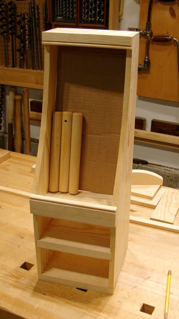
I also needed the thin stock for the angled back of the till section, so I made a cardboard mock-up to determine the correct size. The short hunks of dowels, with orange paint streaks from their days as part of a pipe clamp rack, are standing in for candles.


Once I was finished adjusting the cardboard to get the correct angle and fit, I used it as a template and cut the stock with a knife.


This worked great, much better than trying to saw the flexible wood, but I was a little to aggressive and split off a chunk that ran inside the line - drat! Oh well, the candles will hide that reminder to take it easy.

I glued cleats across the back of the stock to stiffen it and flatten out some cupping it was developing. Because this was cross grain, I only glued the middle couple of inches - a bit of an experiment really, we'll see how it works out.


You can see the pediment, waiting in the background, asking "Weren't you just about to glue me on about an hour ago?"

Yeah, yeah. So I did - and then the back.


The back was nailed on, and here's the tool set for that job:


"What's that? Why yes, that is a 30.06 On A Stick™ and serial #000001 to boot! A true collectors item - thanks for noticing!"

And there it is - just waiting on the drawers...


Final Part VI coming SOON!


Sunday, June 6, 2010

Rainy Day Project


Well, I should have the back deck, phase two, completed by now, but no. Actually, "phase two" is just another way of saying "all the work I didn't finish last summer like I planned." Hmm.

If things had gone like they should have, I'd have cracked on like smoke and oakum and we would now be enjoying the midnight sun on the back deck. But sunny day after sunny day slipped by as I did this and that. When I did try to work on the deck, I first had to figure out what the heck I was thinking when I last stopped. That took most of one day. Then, I had to undo some mistakes I made after misinterpreting what I had been thinking when I last stopped. That took another day. Then I realized that I never ordered enough decking. So I ordered it. It came. So did the rain.

So, I worked in the shop instead. Yea!

While rethinking the deck, I found I had an unneeded pressure treated 4x4. I decided that it should replace the street address post at the end of our driveway - which truth be told was a 1x3, sharpened to a point, driven into the ground with our address scrawled on it with a Sharpie (or possible a Sir Marks-A-Lot). This new post would have spiffy reflective numbers and a decorative cap. The numbers came from the Borg, but the decorative cap was going to come from my shop.

I wanted this to be a quick project, so I worked rather fast and loose, which was actually fun. First I needed to create a horizontal element. For this I wanted a square that would overhang all the sides of the post evenly. Instead of measuring, I used the sliding extension on my folding rule to capture the difference between the width of the stock and the width of the post...


...and then directly transferred that to the face of the stock (marked a line, set the post section to the line and added the extension distance) to determine the correct length to cut. Could I have measured? Sure, but it would have been slower and no more accurate.


I should point out that I wasn't concerned by the rough edge of the board I was using as I planned to round it over. In the end I didn't like how it came out, but if you look closely you can spot it in the background in a later picture.

As the stock I was using was an off-cut from the deck, it had kerfing on one side. This wouldn't do. Time for the scrub plane!


The scrub, followed by the jack, and the stock was ready to go. I used to clamp everything I planed between a bench dog and the vise dog in my end vise. Over time, I've switched to doing most of my planing with the stock just butted against a bench dog, as shown here. Even with side-to-side adjusting (not needed as often as you might think) it's much faster.


Next, I wanted to make a pyramid to top the cap. Some quick layout, and sawing, followed by the trusty jack and there it was:


It was at about this point (no pun intended) that I scrapped the rounded over look for the horizontal square. I decided to make another, and wrap it in mitered moulding. So I dug out the sticking board, selected a profile and got to work.


My sticking board has a built in miter box in the fence, which is handy, if not too accurate.


Lurking in the background is the stair nosing plane I used to round over the edges of the first square.

Since my miters were not great, I needed to adjust them with a chisel. The sticking board made a handy fixture for this.


It is also great for holding the work while drilling, such as for these pilot holes for the nails in the moulding. The fence holds the stock securely with no need for clamping. I do this often, as you can tell by the number of holes in the sticking board.


In the left background is the first square I made, in the right background is the second one, with the first piece of moulding already in place.

I added two more layers of moulding - a thumbnail above the square, and a dropped ogee below it. They came out a little rough, a combination of fast and loose working and not so great stock selection (I ripped some sticks from another decking off-cut). Here's the final cap with all elements in place:


And here it is in place on the actual post at the end of the driveway:


The tool kit used on this project (missing the sticking board).


One of the things I liked about this project was the reminder about the place of perfection. There is a lot more going on in a piece than just perfection of each part. Imperfect parts can be put together into a pleasant whole; perfect parts can be assembled into a ghastly whole. I think the whole (including proportion, character, sense of place etc.) has the overriding influence. Of course, perfect parts can help create a better whole...

P.S. - If you are sharp eyed, and a bit of a photo details nerd (like me), you may have spotted the elusive candle rack on the bench in several photographs. Yep, I'm still working on it...


Wednesday, March 10, 2010

Moulding Samples


When I last posted on my expanding moulding plane shelves the better part of a year ago, I mentioned that I had created a smaller shelf for storing short samples of the mouldings cut by the various planes. I've been slowly adding to these samples and since I find them very useful, I thought I might post about them.

Here's a shot of the almost full shelves:


That lower, center shelf holds the moulding samples:


I make these out of scrap 1x2 pine, and find these useful for several reasons:

1. They allow me to see the positive moulding profile, rather than the "negative" profile on the plane itself. It's funny how different these two versions of the same profile can be - especially for a profile that I haven't used before. I always think I know what the moulding will look like, but somehow my brain never sees it quite right. It works out much better to just work with the positive version.


2. It gives me a three dimensional moulding with which to play. I can see how the light and shadows change in various orientations. The shadow lines on a piece of moulding are a major aspect of the moulding, and they can look very different depending on where the moulding is used. With the sample, I can very easily try the moulding "right-side-up" or "up-side-down" (of course these terms are pretty meaningless - but I think you get the idea). When I'm deciding on a moulding for a piece, I pull out the samples and try them out in their final position. Visualizing is good, but actually seeing it is better.

3. I can stack the samples to see how they would work in building up a compound profile. This isn't perfect, as each moulding would not have to be stuck on a 1x2, but it works well enough to get a good idea of how they would look combined.

4. I use the back of the sample to record information about the plane. I write/draw the maker's mark, the owner's marks, any indicated sizes, and anything else stamped, carved or written on the plane. Then I record the name of the profile, which is sometimes a challenge. I also make note of any quirks in the use of the plane, or reminders to sharpen the iron. Besides being interesting, these notes help me locate the plane in my growing collection.


In the future, I'd like to include the approximate age of the plane on the back of the sample. And of course, I will probably need to make another shelf for the samples, as I underestimated how much room I would need... But what else is new?


Monday, December 7, 2009

Planes and Shavings: Four Portraits


Stanley #49 Tonguing and Grooving Plane


"Andruss" 1/4" Side Beading Plane


Millers Falls #4 Bull Nose Rabbeting Plane


Stanley #3 Smoothing Plane


Wednesday, November 25, 2009

Replacing A Moulding Plane Wedge


The other day I successfully replaced a broken wedge on a side bead moulding plane that I bought on eBay. This was an almost "perfect" project. What made it special was a combination of many of the things I especially enjoy in a project: an old tool brought back to life, using shop-made equipment (successfully), finding a suitable job for a special stash of wood, applying my developing skills to overcome a lingering mental block, and a full and complete project in under two hours. That's a rare single project combination in my shop!

I'd had this plane for a while, but had not been able to use it because the wedge that holds the iron had broken off the very first time I tried to remove it (and yes there is an embarrassing story there, and no, I'm not going to tell it now). I successfully removed the remainder of the jammed wedge from the plane by turning it upside down, clamping the stump of the wedge in the bench vise and lifting the plane body off of it. But that is when the mental block came into play. For some reason I was intimidated by the idea of making a replacement wedge. I'm not sure why, but I convinced myself that this would be a hard thing to do. Stupid. And so this poor plane had been languishing on my desk; the island of misfit tools.

Here's a shot of the original wedge:


The first step was to prepare some stock. I was going to use some oak, when I remembered that my good friend Dave had sent me some hunks of salvaged beech wood, which would be much more appropriate. Thanks again Dave! After cutting a piece and resawing it to approximate thickness, I planed it to final thickness by working against one of my bench dogs. This is a handy trick for thin stock. I also traced the outline of the original wedge (after piecing it back together) on the new blank.


Taking it over to my saw bench, I used the slot in the overhanging end as a birdsmouth and cut out the shape of the wedge and finial with a coping saw.


To ensure that the straight edges of the wedge were true, I used a plane. It's difficult to secure small pieces and accurately plane them, so in this case I found it much easier to hold the plane in the vise and push or pull the wedge along the plane. Kind of like a miniature power jointer - only without the power :)


I cleaned up the finial curves with a file, and after some trial and error adjustments to the wedge angle, I had what looked and felt like a good fit. But there was only one way to be sure. A quick trip to the Scary Sharp bench, and the ca. 1850 Winsted plane was ready for a test drive on the sticking board; it worked great!


And here's a final shot of the now happy plane, ready to join its brethren on the shelves:


Sunday, June 28, 2009

More Shelves for More Moulding Planes


As I've mentioned in the past, I'm fairly addicted to moulding planes. My collection (all users, of course) has been growing steadily and it was time to make some additional shelves. At first, I was just going to make a third unit using the same design as the first two, but with a different top profile. But after looking at the space available, and visualizing the three shelving units as a whole, I decided to make this unit larger to serve as a sort of center piece, flanked by the two existing units.

Here's the plan I came up with on paper:


The smaller bottom shelf is for holding short sections of moulding profiles, as well as my plane hammer.

Here's the stock waiting for layout. The sides and bottom are full width, but the shelves are narrower to allow the back to be set into rabbets, hence the panel gauge.


The four shelves are housed in dadoes. There are a lot of ways to cut dadoes, but after trying most, I've settled on using the tool dedicated to that purpose - the wooden dado plane. For this project, I used a plane that my fried Dave sent me. It was fast and easy; thanks Dave!


Next came the shaping of the tops and the rabbets. Each side is topped with an ogee, or cyma recta, which has the upper section concave and the lower section convex. Layout was simple with a pair of dividers. I cut the curve with a turning saw and cleaned it up with spokeshaves. As this is strictly shop furniture, I didn't bother with stopped rabbets - so if you are extremely tall or very short, you'll be able to see the gaps. I can live with that.


Here's a shot of the shelves in place. All three are hanging on French cleats, which I use for hanging almost everything in the shop. If you are not familiar with these, they are two cleats, one screwed to the wall and one to the shelves (or whatever), with complimentary 45° bevels. This system uses the weight of the shelves to lock them to the wall. It's simple, strong, and very flexible. These interlocking cleats are visible in the photo below if you look very closely at the top, rear of the right-most unit.


And with the moulding planes home to roost:


This one's just a fun detail shot:


Traditionally, I end a project post with a shot of all the tools used on that project. This time I am going to do things a little differently; I'm writing a separate post with shots of the tools in task groups. I'll try to have that up in the next day or so...